
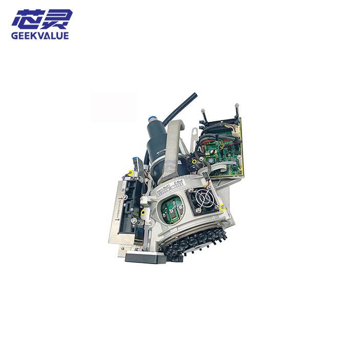
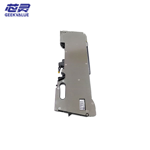
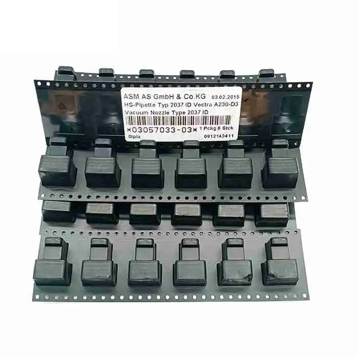
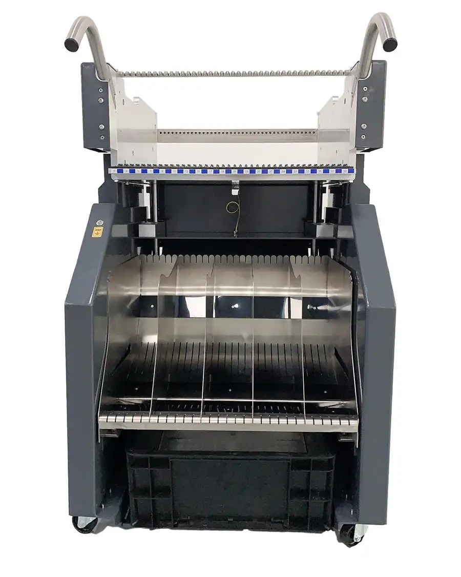
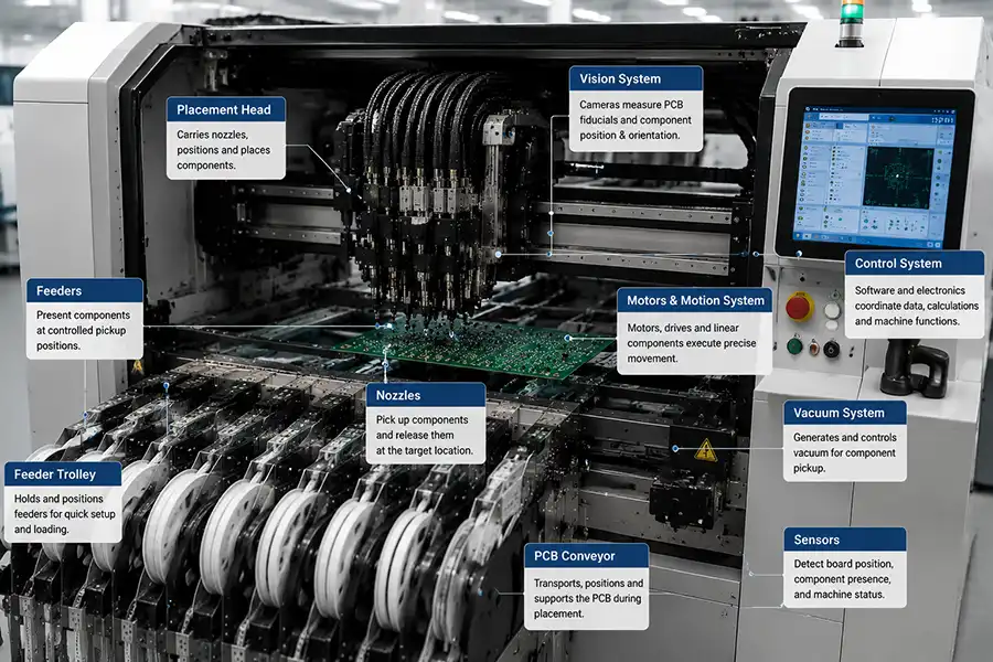
The main parts of an SMT pick-and-place machine include component-supply systems, nozzles, placement heads, vision systems, control electronics, motors and motion components, PCB-handling systems, vacuum and sensor systems, and feeder trolleys. Each has a distinct responsibility, and accurate component placement depends on their coordinated operation.
Feeder Presents → Nozzle Picks and Releases → Placement Head Carries and Positions → Vision Measures → Control System Calculates and Coordinates → Motion System Executes Movement → Conveyor Transports and Supports the PCB
Exact hardware arrangements vary by machine generation and configuration, but the main functional responsibilities remain broadly similar.
SMT Feeders and Component-Supply Systems
SMT feeders and other component-supply systems make components available at controlled pickup positions.
Components may be presented through:
Tape feeders
Tray systems
Tubes or sticks
Other supported presentation systems
A feeder may advance or present the next component for pickup, but it does not place the component onto the PCB. After the feeder presents the component, the nozzle holds it, the placement head carries it and the controlled motion system moves it through pickup and placement.
For component-presentation requirements, review available SMT feeders and confirm that the feeder family matches the installed machine platform and configuration.
SMT Nozzles and Pickup Tools
An SMT nozzle or pickup tool directly contacts the component during pickup and placement.
Its main functions include:
Contacting the component at the supply position
Holding it during movement and measurement
Releasing it at the placement location
Vacuum is commonly used to hold many surface-mount components, although other pickup methods may be used for components with different shapes or handling requirements.
The nozzle is not the complete placement head. The nozzle contacts, holds and releases the component, while the placement head carries and positions the nozzle.
For replacement tooling that directly contacts the component, review available SMT nozzles. Suitability depends on the component shape, handling requirements and installed machine configuration.
SMT Placement Heads
The SMT placement head is the moving assembly that carries one or more nozzles or pickup tools.
A placement head may:
Carry pickup tools between supply, measurement and placement positions
Support controlled positioning and rotation of the pickup tools
Lower the component toward the programmed placement location
The head works with vision, control and motion systems, but it does not perform their responsibilities. Vision measures, the control system calculates and coordinates, and the motion system executes movement.
When the required item is the tool-carrying assembly rather than the nozzle itself, review available SMT placement heads and confirm the installed head type, machine generation and configuration.
Vision and Camera Systems
Machine vision measures PCB and component conditions that support accurate placement.
Vision systems may support:
PCB fiducial recognition
Component-presence confirmation
Component-position measurement
Component rotation and orientation measurement
Shape, edge or feature recognition
Vision produces measurement data rather than physically moving the component or independently executing placement.
Vision Measures → Control System Uses the Data → Motion System Executes the Corrected Movement
Control Systems, Software and Electronics
The control system coordinates production information, measurement data and machine actions.
It may manage:
Production-program data
PCB and component coordinates
Vision measurements
Placement sequence
Motion commands
Sensor feedback and error handling
Supporting electronics may include control boards, industrial computers, communication modules, driver electronics and interface boards.
The control system calculates corrections and coordinates commands, while motors, drives and motion components execute the resulting mechanical movement.
Motors and Motion Systems
Motors and motion systems physically execute controlled machine movement.
They may drive:
Placement-head movement
Axis and gantry positioning
Rotational movement
PCB conveyor movement
Other supported machine mechanisms
Related components may include motors, drives, encoders, belts, pulleys, bearings, linear guides and couplings.
For motor- or drive-related replacement requirements, confirm the electrical rating, connector, mounting arrangement and exact part identity before reviewing available SMT machine motors.
PCB Conveyor and Board-Handling Systems
PCB conveyor and board-handling systems transport, position and support the board inside the placement machine.
These systems may:
Transfer the PCB into and out of the machine
Stop or physically position the board
Clamp or support it during placement
Adjust for different board widths
Coordinate board transfer with connected equipment
Related parts may include conveyor belts, rails, stops, clamps, board supports, sensors and width-adjustment mechanisms.
The conveyor transports and physically supports the PCB, while vision, position sensors and the control system help establish the board’s actual relationship to the programmed placement coordinates.
Vacuum, Pneumatic and Sensor Systems
Vacuum, pneumatic and sensor systems support component holding, machine feedback and operating safety.
They may include:
Vacuum generators and valves
Air tubing and filters
Pressure or vacuum sensors
Component-presence sensors
Position sensors
Safety sensors
Vacuum may help the nozzle hold a component, while sensors provide information about pickup, position, presence or machine conditions to the control system.
Vision components, electronic modules, conveyor parts, sensors and pneumatic components may be found within the broader More SMT Parts category when they do not have a dedicated product section.
SMT Feeder Trolleys and Supporting Equipment
An SMT feeder trolley is supporting equipment used to store, organize or transport feeders.
A feeder trolley may support:
Feeder storage
Movement between preparation and production areas
Offline feeder preparation
Changeover organization
Transport of loaded feeders near the production line
The feeder and trolley perform different functions:
Feeder: Presents components at a controlled pickup position.
Feeder trolley: Stores, organizes or transports feeders.
The trolley does not feed components inside the machine and does not pick or place components.
For feeder storage and transport requirements, review available SMT feeder trolleys and confirm their suitability for the feeder family and physical configuration.
How the Main SMT Machine Parts Work Together
| Function | Main System or Part |
|---|---|
| Present components | Feeder or other supply system |
| Contact, hold and release components | Nozzle or pickup tool |
| Carry and position the pickup tool | Placement head |
| Measure PCB and component position | Vision system and relevant position sensors |
| Calculate corrections and coordinate sequence | Control system |
| Execute controlled movement | Motors and motion system |
| Transport and support the PCB | Conveyor and board-handling system |
| Store and move feeders | Feeder trolley |
These systems cooperate during production, but measurement, calculation and mechanical execution remain separate responsibilities.
What to Confirm Before Ordering a Replacement SMT Part
Knowing the general part category is only the first step. Similar-looking components may have different electrical, mechanical or software requirements.
Before ordering, confirm:
Machine model or generation
Complete part number and suffix
Brand or manufacturer markings
Physical dimensions
Connector and mounting arrangement
Clear photos
Installed location
This information supports part identification, but final compatibility should be confirmed using exact machine and part documentation.
Explore ASM/SIPLACE SMT Machine Parts
Start with the part’s function: component presentation points to feeders, direct component contact points to nozzles, pickup-tool movement points to placement heads, mechanical movement points to motors, and feeder storage or transport points to trolleys. Vision, electronic, conveyor, sensor and pneumatic requirements may fall within the broader SMT machine parts category.
After identifying the likely category, confirm the exact item using the machine model, complete part number and suffix, installed position, connector or mounting details, clear photos and required quantity.
Frequently Asked Questions About SMT Pick-and-Place Machine Parts
What are the main parts of an SMT pick-and-place machine?
The main parts include component-supply systems, nozzles, placement heads, vision systems, control electronics, motors, conveyors, sensors, vacuum components and supporting equipment such as feeder trolleys.
What is the difference between an SMT feeder and an SMT nozzle?
The feeder presents a component at a controlled pickup position. The nozzle contacts, holds and releases the component.
What is the difference between a placement head and a nozzle?
The nozzle directly contacts the component, while the placement head carries and positions the nozzle or other pickup tool.
What does the vision system do in an SMT machine?
The vision system measures PCB or component position, orientation and recognizable features. The control system uses this data to calculate corrections, and the motion system executes the resulting movement.
What is an SMT feeder trolley used for?
A feeder trolley stores, organizes and transports feeders for preparation or changeover. It does not present components inside the machine or perform component placement.
Are SMT machine parts compatible across different SIPLACE models?
Compatibility should not be assumed. The machine model, generation, configuration, part number, suffix, connector and mounting arrangement must be verified.
Conclusion: The main parts of an SMT pick-and-place machine perform separate but coordinated responsibilities: feeders present components, nozzles contact and hold them, placement heads carry the pickup tools, vision systems measure, control systems calculate and coordinate, motion systems execute movement, conveyors transport the PCB and trolleys organize feeders. Understanding these distinctions helps users identify the relevant SMT parts category before confirming an exact replacement part.